Complete modernization of a printing machine with the implementation of a Lenze automation system
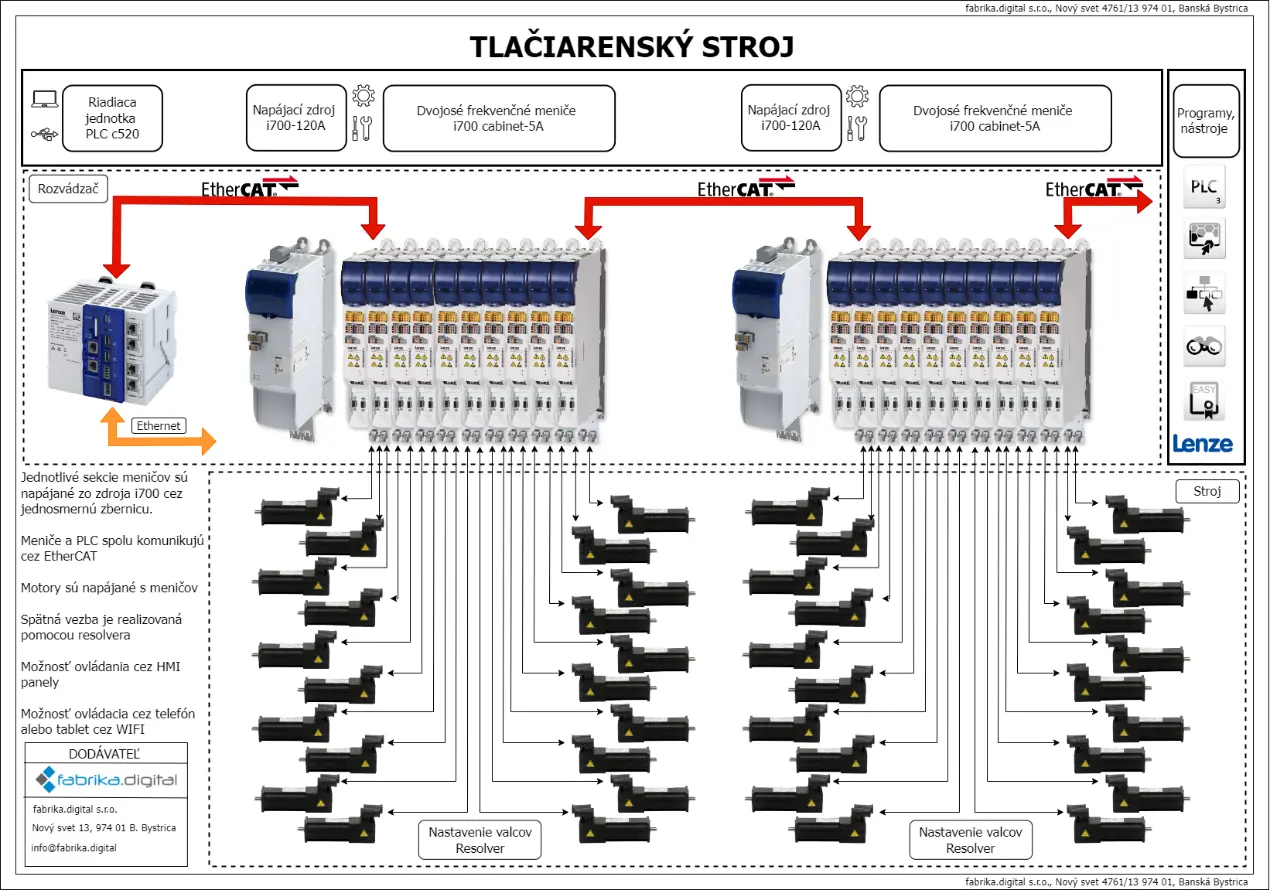
The scope of the project involved a comprehensive modernization of an older eight-color printing machine whose original control system suffered from frequent failures, unstable communication, and a high level of unplanned downtime. The objective was a complete migration to a modern Lenze automation platform in order to increase reliability, serviceability, and technological accuracy of the equipment. The machine was based on a central impression cylinder acting as the main synchronized drive of the entire line. The individual colors were divided into 8 sections, each containing 7 controlled drives. The machine also included an unwind and rewind section equipped with 4 drives. The technological equipment was complemented by heating ovens and fans ensuring proper drying and process stability. The total number of machine axes was 62, making it a highly complex modernization project.
CUSTOMER REQUIREMENTS
- Replacement of the existing control system with a new Lenze platform (C520) and complete reprogramming of the printing machine
- Replacement of existing Lenze 9300 frequency inverters with new drive units
- Replacement of the legacy CANopen communication with a new EtherCAT network
- Installation of new Lenze v430 HMI panels, development of a new visualization interface, and implementation of remote machine control
- Modification of the safety wiring, reorganization of the control cabinet, and disconnection/removal of all unnecessary components (cabling, protection devices, chokes, power supplies, etc.)
- Implementation of shared remote access for machine identification, diagnostics, and service via an industrial Teltonika router
- New electrical documentation
BLOK DIAGRAM
USED COMPONENTS
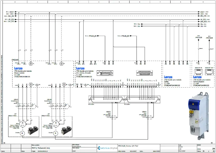
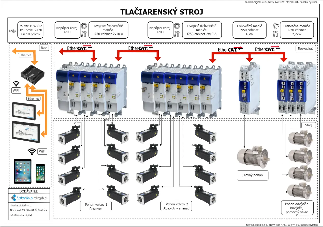
As shown in the block diagram, the control system was based on a Lenze C520 PLC. Two Lenze v430 HMI panels in 7" and 15" sizes were used for visualization and operation. Remote machine control was implemented via a mobile device with the possibility of further functional expansion. Dual-axis Lenze i700 drives were used for positioning axes, while printing and anilox rollers were controlled by dual-axis Lenze i750 drives. The advantage of these drives lies in the use of a single power supply per drive section with interconnection via a common DC bus. Drives in the unwind section were upgraded to Lenze i950 units, which were also used for the main central drive of the machine.
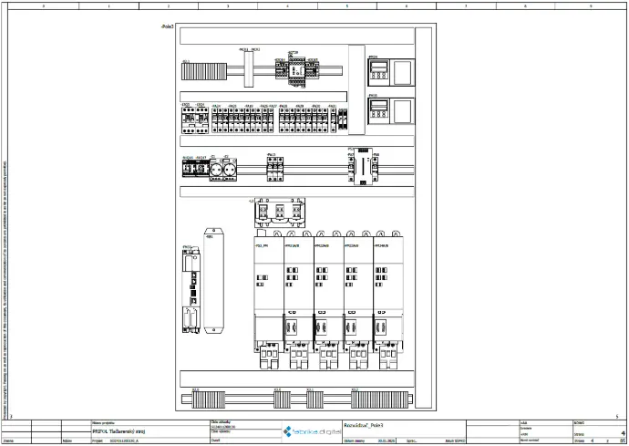
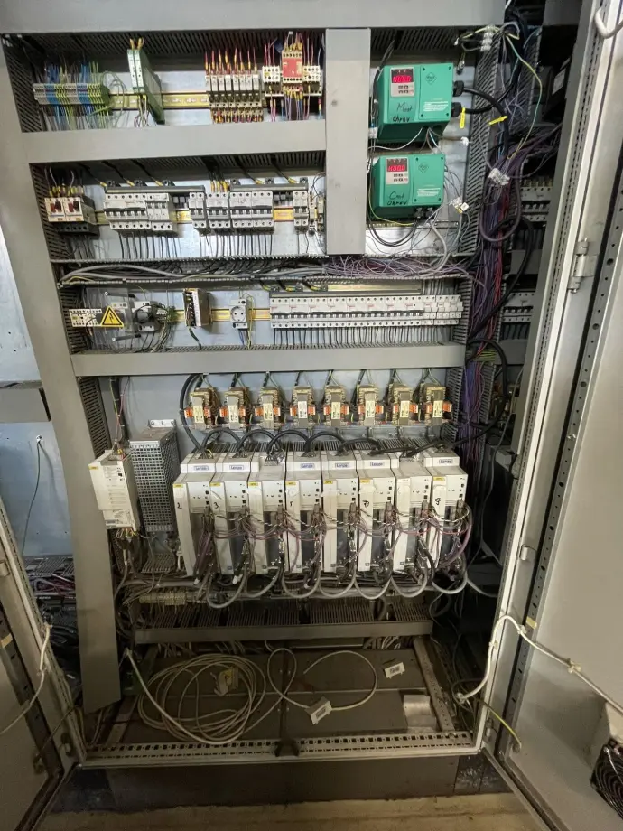
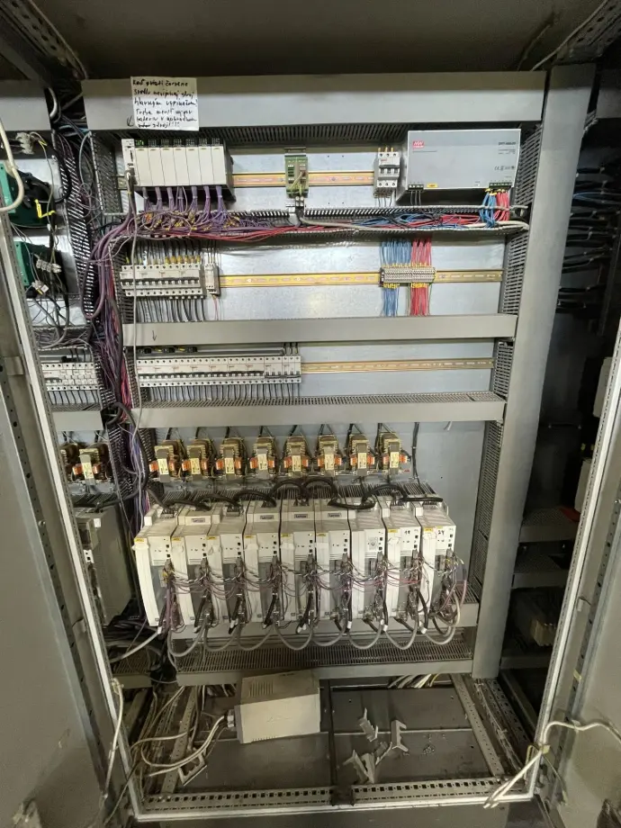
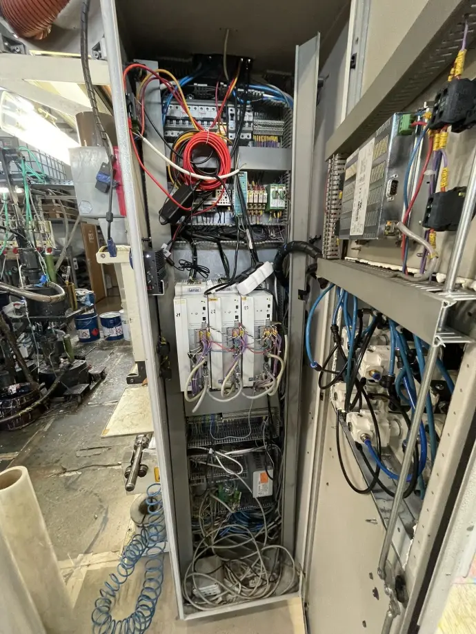
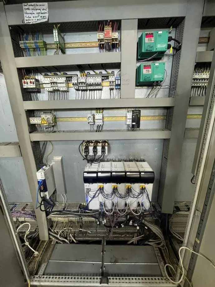
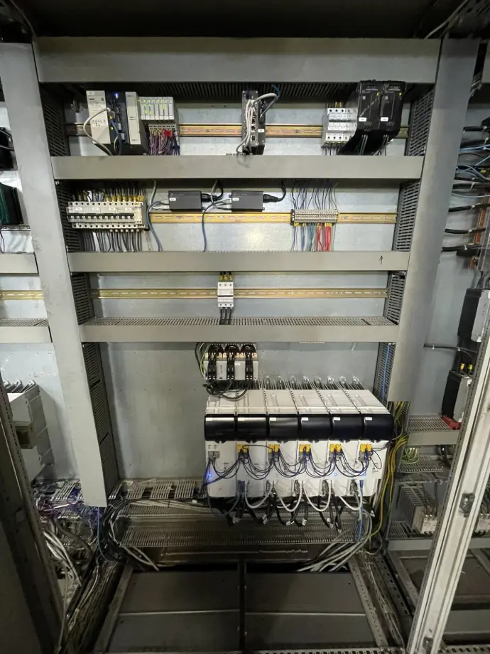
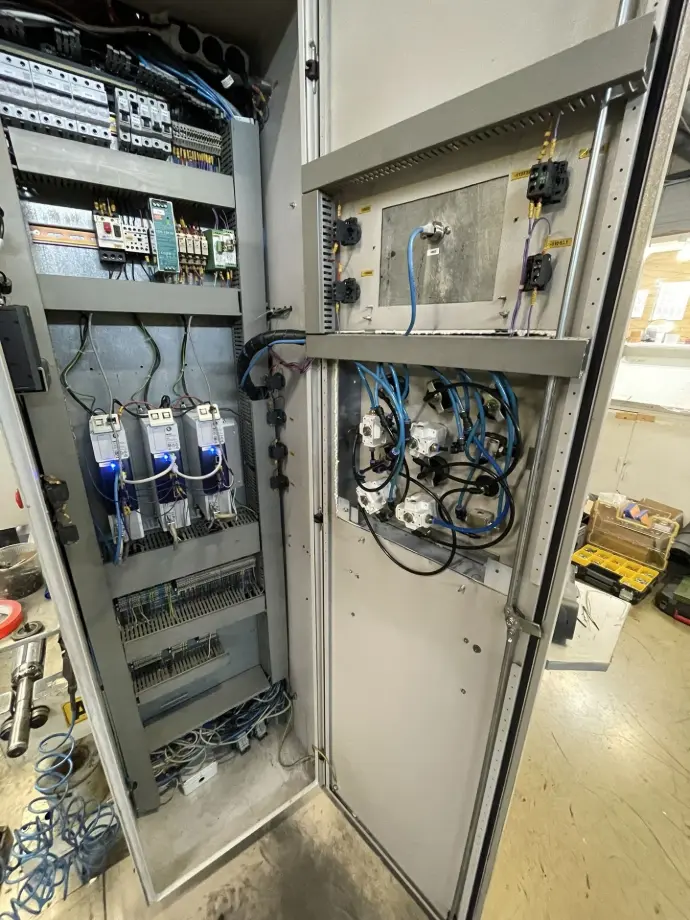
CONTROL CABINETS
As part of the modernization, the original frequency inverters installed in all control cabinets were completely replaced with new drive units. The drives were divided into four power sections according to the technological parts of the machine. By implementing Lenze i700/i750 series inverters, the power architecture of the cabinets was significantly simplified, since each section required only a single power supply unit, one line choke and one main circuit breaker, while the individual drives were interconnected via a common DC bus. This DC bus coupling also provides a positive effect on the transfer of regenerated energy during drive deceleration, reducing the overall thermal load of the system.
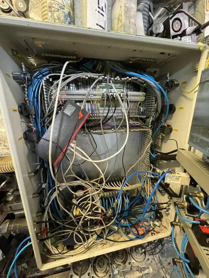
The original control system consisting of two PLCs was replaced by a single Lenze C520 PLC together with distributed I/O modules. The CANopen communication bus was replaced by a deterministic EtherCAT network, resulting in higher control speed and improved reliability. During the reconstruction, all unused components were removed from the cabinets, the safety architecture was simplified, and the overall wiring layout was optimized. As a result, both cabling complexity and service accessibility were significantly improved compared to the original installation.
From a hardware architecture perspective, the machine was divided into three main control cabinets:
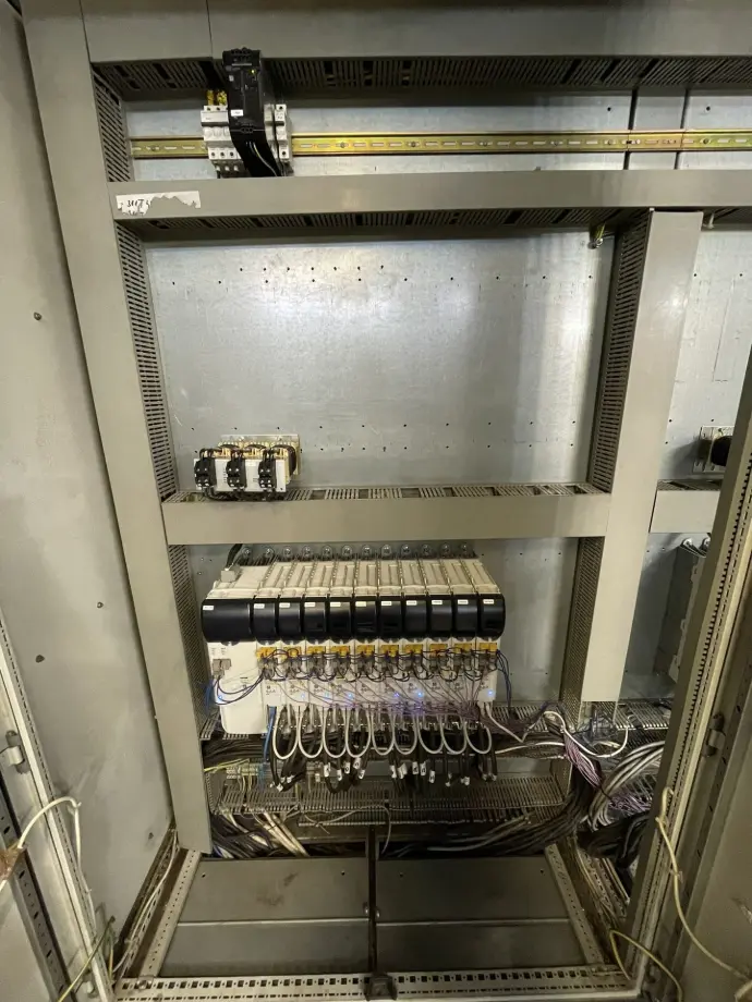
• Main cabinet - containing four sections of Lenze i700 and i750 drives, an i950 inverter for the main central drive, additional drives for heating fans and heaters, as well as protection and power distribution components.
• Winder and unwinder cabinet - dedicated to tension control and regulation of winding and unwinding processes. This cabinet includes three Lenze i950 drive units.
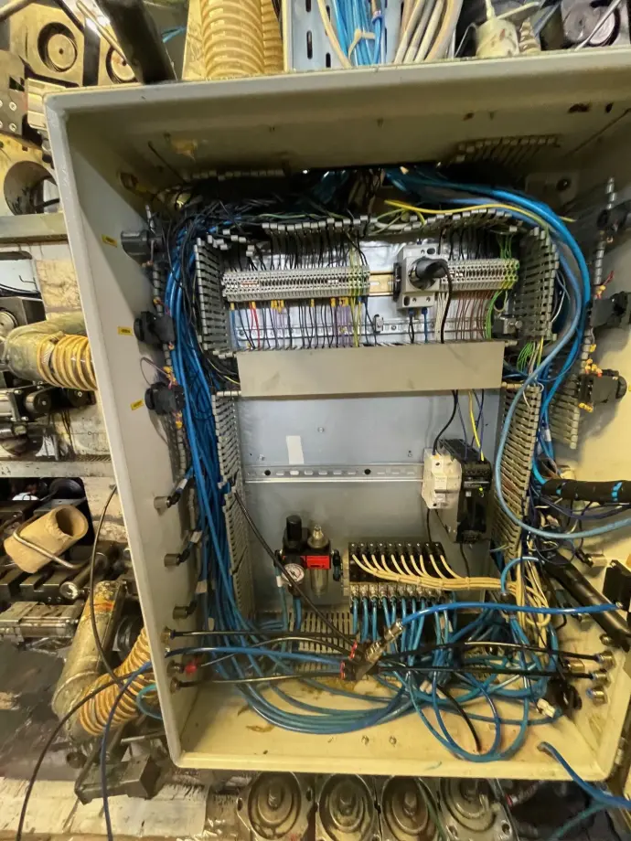
• Control cabinet - housing pneumatic control valves, operator pushbuttons and the main HMI panel.
HMI PANELS AND VISUALIZATION
Two operator HMI panels are installed on the machine. The smaller 7" panel is located on the winding cabinet and is primarily used for local control and diagnostics of the winding process. The main 15" panel is mounted on the main control cabinet and provides full technology visualization, including machine control, parameter setup, and service functions.
Both panels are Lenze v430 units communicating via industrial Ethernet. A key advantage of these panels is the support of Power over Ethernet (PoE), allowing both power supply and data communication to be transmitted through a single shielded FTP cable. This solution simplifies cabling, reduces the number of power supplies required in the cabinet, and minimizes the risk of interference or wiring errors.
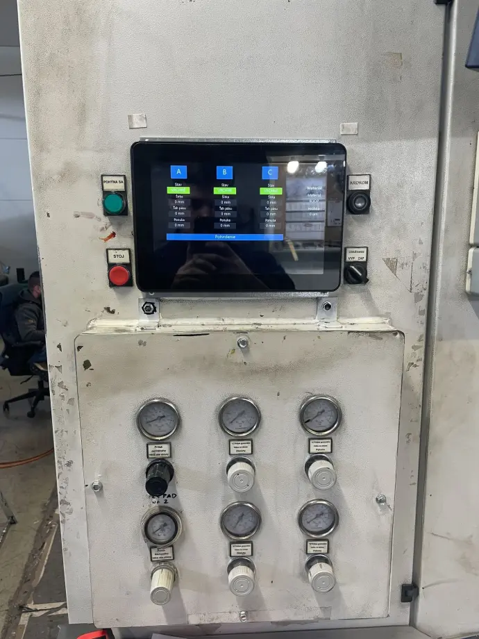
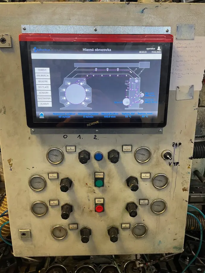
The visualization was implemented in the CODESYS WebVisu environment, where the visualization layer architecture is directly integrated with the PLC application. A dedicated visualization configuration was created for each HMI panel, optimized according to the display resolution and functional purpose of the respective screen. The local 7" panel provides the operator with quick access to basic winding controls, status indicators, and diagnostic functions, while the main 15" visualization includes extended technological screens, parameterization menus, service modes, and detailed alarm and status messages.
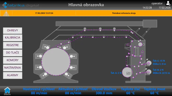
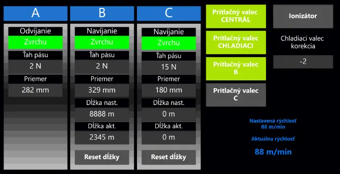
For simplified machine setup and operation, a remote control solution was also delivered. This consisted of a mobile phone with an independently developed visualization interface. The “controller” is used for adjusting individual printing sections, fine-tuning slip parameters and setting the pressure against the main cylinder. Thanks to the wireless connection, the operator is able to configure the machine from virtually any position, including directly from behind the inspection camera monitoring the printing process.
PROGRAMMING
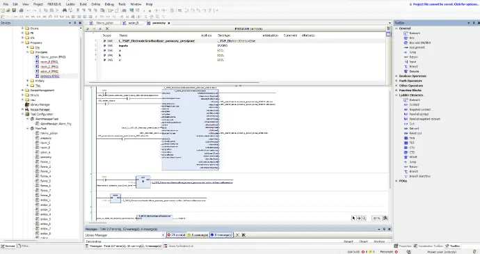
As part of the modernization, the control system was completely reprogrammed in the Lenze PLC Designer environment, where a new motion-control architecture based on a master-slave drive synchronization concept was implemented. The industrial EtherCAT fieldbus was implemented as the communication infrastructure between the individual parts of the control system, ensuring deterministic real-time data exchange between the PLC, drives and distributed I/O modules. The initial step of the implementation involved precise configuration and recalculation of the incremental encoder pulses of the main cylinder, which serves as the reference axis for the entire technological process. Based on this reference value, all remaining drives were subsequently synchronized.
After the encoder setup, the next stage focused on the winding and unwinding process. For this purpose, the Lenze FAST – Winder Tension Control application module was used, specifically designed for precise tension regulation in continuous processing applications. The module calculates the current winding diameter based on speed ratios and a mathematical model, enables dynamic adjustment of the tension force, and supports tension control according to a predefined tension curve depending on the increasing roll diameter.
Within the winding section, an auxiliary material pull roller was also implemented, operating in synchronous speed mode relative to the main cylinder. This drive allows controlled slip adjustment with respect to the master axis, enabling fine tuning of the material tension between the printing and winding sections without affecting the base line speed.
After successful testing of the winding and unwinding process, the implementation of the printing control itself followed. The printing machine consisted of eight printing sections, each representing an individual color unit. Mechanically, each section was composed of an anilox roller and a printing cylinder, where the anilox roller meters the ink onto the printing cylinder, which then transfers the image directly onto the foil guided over the main central impression cylinder.
From a motion-control perspective, each printing section was designed as an independent multi-axis system. Both the anilox roller and the printing cylinder were equipped with a pair of positioning drives for radial movement towards and away from the main cylinder, allowing precise adjustment of pressure and working distance during technological operation. The printing cylinder was additionally equipped with a dedicated linear drive for axial movement, used for fine lateral register correction (left–right) during machine operation. In total, each printing section included seven controlled drive axes.
From a synchronization perspective, the printing cylinders had to be precisely synchronized with the main cylinder in order to eliminate print smearing caused by phase shifts or speed instability. During programming, the Lenze FAST Sync & Correction block was used for this purpose. It is an application motion module designed for accurate axis synchronization and dynamic position correction during machine operation. It is mainly used in printing, packaging and converting lines, where multiple drives must follow a reference (master) axis while still allowing fine adjustments without interrupting production.
For the anilox rollers, precise synchronization was not required; they operated in speed mode as subordinate axes, following the speed of the printing cylinders. As part of the implementation, a homing sequence was also programmed to define the machine’s base technological position. Once the reference cycle was initiated, all axes automatically moved to their initial positions. For both the printing and anilox rollers, this meant rotating to the upper angular position, allowing simple and safe installation of printing plates and easier handling of printing components.
The drives responsible for the radial movement of the rollers and for adjusting the printing gap performed their homing procedure based on position sensors. Each axis had a precisely defined reference point derived from the sensor, which established the zero position for subsequent technological movements.
After successful testing of all drives, homing cycles and synchronization links, a test print was initiated in technological operation mode. During the trial run, specific customer requirements were progressively implemented into the control program, particularly print correction functions, various working positions of the sections towards the printing position, service positions for cleaning, and automated sequences for the replacement of printing components. At the same time, full management of the technological system’s inputs and outputs was integrated into the PLC application, including control of oven heaters, fans and exhaust systems, operator pushbuttons, the edge guiding system and the corona treatment unit for the foil. Individual technological functions were linked to the HMI visualization, enabling centralized control, diagnostics and parameterization directly during machine operation
REMOTE ACCESS
As part of the project, remote access to the machine was implemented via an industrial Teltonika router. The solution enables clear device identification, remote fault diagnostics, control system parameterization, and the execution of service interventions without the need for the physical presence of a technician on site. The implementation of remote access significantly reduced response times during service operations.
ELECTRICAL DOCUMENTATION
After the successful reconstruction of the control cabinets and completion of the control system programming, the next step was the preparation of a fully updated electrical documentation reflecting the new machine wiring configuration. The objective was to ensure clear circuit identification, simplify fault diagnostics, and provide a structured basis for future service and technology expansion. The electrical documentation was developed in EPLAN Electric P8 and included detailed multi-page schematics of both power and control circuits, covering the interconnection of drives, safety components, distributed I/O modules and the EtherCAT communication infrastructure. In addition to wiring schematics, 2D mounting layouts of individual control cabinets were created, showing the precise placement of components. The documentation therefore provides a complete digital reference for servicing, diagnostics and potential future machine modifications.