Shielding between frequency inverter and motor
Proper implementation of shielding for the power cable between the frequency inverter and the electric motor is one of the most important factors influencing the electromagnetic compatibility (EMC) of the drive system. Improper or insufficient shielding causes increased electromagnetic emissions, which may manifest as interference in measurement and control circuits, unreliable communication between devices, or, in extreme cases, as unwanted inverter shutdowns and damage to the motor bearings.
Modern frequency inverters use fast semiconductor switches (IGBT transistors) that generate very steep voltage edges (typically up to several kV/µs). These high-frequency voltage components are transmitted through the power cable to the motor, creating parasitic capacitive and inductive couplings. If the cable is not shielded, or if the shielding is connected improperly, the cable effectively becomes an antenna that emits broadband electromagnetic interference. This, in turn, affects the operation of nearby devices – particularly PLC controllers, sensors, fieldbus communications (e.g., Profinet, CANopen, EtherCAT), and low-voltage signal circuits.
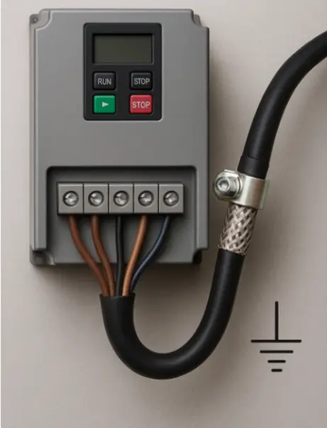
From the perspective of drive system design, it is therefore essential to use symmetrical, shielded motor cables with dense copper braiding (at least 85% coverage), with the shielding grounded at both ends – directly at the inverter output and at the motor frame. The grounding must be implemented with a 360° contact (e.g., using EMC clamps), not with a long single-sided conductor (“pigtail”), which significantly increases the connection impedance for high frequencies. Improperly connected shielding often reduces its effectiveness by tens of decibels.
The technical significance of shielding and 360° grounding in drive systems
Properly designed and implemented shielding of power cables between the inverter and the electric motor serves to limit the propagation of high-frequency electromagnetic interference (EMI) into the surrounding environment. Frequency inverters use fast switching power transistors (IGBT, MOSFET) with typical voltage edge rates in the range of 2–10 kV/µs. These rapid voltage changes induce high-frequency currents in the parasitic capacitances between phase conductors, cable shielding, and ground.
If the shielding is connected only on one side or by means of a long, thin conductor (“pigtail”), a high-frequency impedance is created, preventing these interference currents from being properly discharged to ground. As a result, the interference is radiated into the surrounding space and coupled back into the control circuits, which may lead to:
• interference with analog signals (e.g., from encoders or sensors)
• faulty states of the PLC or fieldbus systems (e.g., Profinet, EtherCAT, CANopen)
• excessive bearing currents in the motor
• activation of inverter protective functions (Earth Fault, Leakage, DC bus error)
Why 360° contact is important ?
Effective shielding works only when its surface behaves like a Faraday cage that fully encloses the cable. Therefore, the shielding must be electrically connected over the entire circumference (360°) and at both ends:
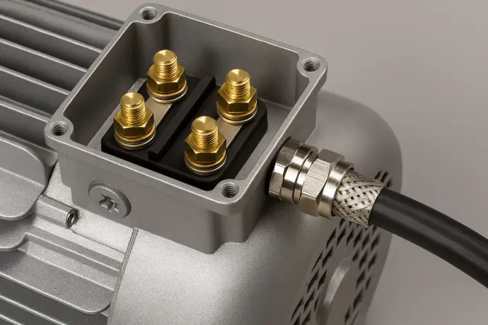
• at the inverter output – directly to the grounded metal part of the enclosure or to a dedicated EMC grounding bar
• at the motor entry – to the metallic housing of the motor or the terminal box
To achieve this type of connection, EMC clamps and cable
glands are used, which provide a spring-loaded or metallic
contact around the entire circumference of the cable braid.
Such a connection has low impedance even at high
frequencies (in the range of milliohms to microohms),
effectively diverting interference currents to ground and
preventing their radiation.
Why the “pigtail” doesn’t work ?
The use of a so-called “pigtail” – a single stripped wire taken from the cable braid and connected to the PE terminal – is a common mistake that completely degrades the effectiveness of shielding. From a high-frequency perspective, such a wire behaves as an inductance; even a 10 cm length can have an impedance of 30–50 Ω at 10 MHz. This means that instead of diverting interference currents to ground, it creates voltage differences, causing the shield to act like an antenna and worsening EMC performance by 20–40 dB. In practice, this can make a system that would otherwise comply with EN 61800-3 suddenly fail.
Why grounding at both ends is important ?
It is sometimes claimed that “the shielding should be grounded only on one side to avoid ground loops.” This was true for low-frequency signals (e.g., audio or analog measurement), but not for high-frequency currents generated by frequency inverters. In drive systems, it is essential to ground the shielding at both ends because:
• it reduces the overall impedance for high-frequency currents
• interference currents have a shorter return path
• radiation along the cable length is eliminated
• the risk of induced voltages on the machine structure is minimized
Qualitative difference – measurable values
Type of shielding connection Noise attenuation (at 10 MHz)
360° EMC clamp on both ends > 60 dB
360° connection on one end only 25–30 dB
Pigtail on one end < 10 dB
Conditions for achieving maximum shielding effectiveness
Use of a suitable cable
• Symmetrical three-phase motor cable designed for frequency inverters
• Dense copper braid shielding – at least 85% coverage
• Suitable insulation with low capacitance and high thermal resistance
Grounding of the shielding at both ends
• The shielding must be electrically connected to both the inverter frame and the motor frame
• This ensures low impedance for high-frequency currents and a closed return path
Use of 360° EMC contact
• The grounding must be implemented over the entire circumference of the braid, not with a single wire
• Preferably achieved using EMC clamps, cable glands, or terminal blocks with flat contact surfaces
Minimal length of unshielded sections
• The braid should not be stripped longer than 2–3 cm
• Every additional centimeter increases radiation and reduces shielding effectiveness
Avoid the use of a “pigtail”
• A single stripped wire taken from the braid (the so-called pigtail) degrades shielding effectiveness by up to 90%
• Its high-frequency impedance prevents interference currents from being properly diverted
Reliable connection to grounding (PE)
• EMC clamps must be firmly attached to a grounded metal structure or grounding bar
• The surface must provide conductive contact (free of paint, coating, or oxidation)
Proper cable routing
• Power cables should be routed separately from signal and data lines
• If crossing is necessary, it should be done at a right angle
• Avoid running cables in parallel with communication lines (Profinet, CANopen, etc.)
Grounding of the entire system
• All metal parts (enclosures, cabinets, motor, supporting structures) must be bonded to the same potential
• This eliminates the formation of potential differences and ground loops
Use of EMC cable glands and filters at cabinet entry/exit points
• They prevent interference from penetrating through the metal wall of the enclosure.
• They maintain continuous shielding even where the cable passes through.

