It was a large overhead construction crane, where the customer’s requirement was to modernize the original drive for the load travel in the X-axis (forward/backward along the crane bridge). Originally, a decentralized frequency inverter was installed directly on the motor housing. This system had to be replaced with a new solution, in which the frequency inverter was relocated into the main crane switchgear. The drive provided load movement in both directions with the possibility of operation at three different speed levels.
CUSTOMER REQUIRMENTS
- Ununstalling of the old frequency inverter from the motor
- Installation of the new frequency inverter into the switchgear cabinet
- Replacement of the power and control cabling between the inverter and the motor
- Programming and commissioning
REPLACEMENT AND PROGRAMMING OF THE FREQUENCY INVERTER
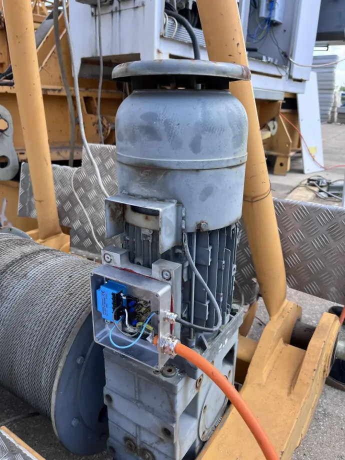
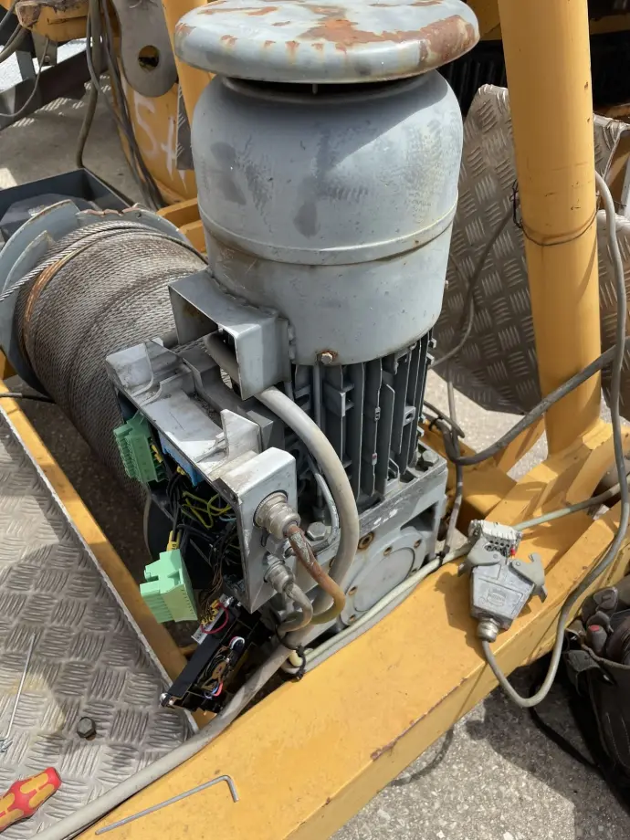
The first step of the modernization was the dismantling of the original Lenze Motec frequency inverter, which was installed in a decentralized way directly on the electric motor. This motor was located at the beginning of the crane bridge structure and provided the load travel in the X-axis. After removing the inverter, its position was replaced with a metal installation box with outdoor protection rating, which also served as a cover for the motor terminal block. Inside this box, a single-phase rectifier was installed, required for powering the motor’s electromagnetic DC brake, since the new frequency inverter no longer featured a built-in source for brake control. This solution ensured reliable protection of the terminal block, created space for connecting the new power and control cabling, and at the same time enabled full functionality of the motor brake.
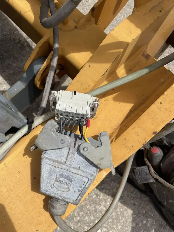
In the final configuration, only a single combined cable was routed from the switchgear to the motor, containing both the supply conductors for the motor and separate conductors for powering the electromagnetic brake. This solution reduced the number of cables, thereby eliminating potential sources of failure and increasing overall operational reliability.
Another advantage was improved safety, since the new cable runs through the walkable section of the crane bridge structure. By using a single robust cable, the risk of mechanical damage, tripping hazards for operators due to loose wiring, or abrasion of the cables during operation was significantly reduced.
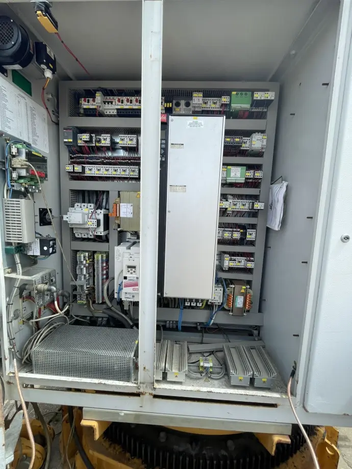
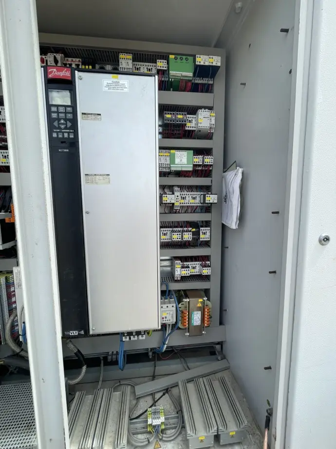
The new frequency inverter was integrated into the existing crane switchgear. Due to space constraints, it could not be mounted on the main mounting plate and was therefore installed on the side wall of the switchgear. Along with the inverter, a new braking resistor was also installed inside the cabinet, which had originally been located near the electric motor. The frequency inverter used was a Lenze i550 with a power rating of 5.5 kW.
The inverter control was implemented exclusively via digital inputs and outputs, without any communication bus. The original concept, in which the control signals were routed directly to the motor with the integrated inverter, was removed along with the associated cabling infrastructure after dismantling. In the new configuration, all control circuits were routed directly within the switchgear and connected to the terminals of the new inverter. The digital inputs of the inverter were configured to control the rotation direction (forward/backward), to activate and deactivate the electromagnetic brake, as well as to process safety signals (emergency stop, limit switches).
A critical element was the control of the motor’s electromagnetic brake, where the timing of activation and release had to be correctly set in relation to the inverter’s operation to ensure safe and reliable performance. After completing the parameterization, the functionality of movement in both directions at all three speed levels was tested, along with the operation of the electromagnetic brake and the system’s response to emergency stop and limit switches.