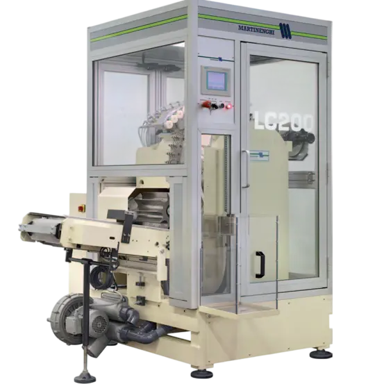
The Leakage test LC is a specialized part of the production line for processing metal tubes. Its purpose is to ensure the handling and sorting of tubes between individual technological operations.
The tubes are fed into the conveyor and subsequently picked up by two synchronously operating “butterfly” arms. Each arm is designed to simultaneously grip and transfer 8 tubes at once. After being picked up, the tubes are subjected to a leakage test, performed pneumatically – compressed air is supplied into each tube and any pressure drop or leakage is monitored. The entire test takes less than 2 seconds.
Based on the leakage test results, the tubes are automatically separated:
- non-defective tubes (without leakage) are smoothly transported to the next stage of the production line for further processing,
- defective tubes (with leakage) are rejected by an ejection mechanism and removed from the line to prevent their further processing.
CUSTOMERS REQUIRMENTS
- Replacement of the control system and HMI panel
- Replacement of frequency inverters for drives
- Complete replacement of the switchgear cabinet
- Reprogramming of the machine to the new control system
- Creation of a new visualization for control
- New machine safety
- Electrical design + operating manual
Preparation
Electrical schematic design, Control cabinet wiring
Installation
Installation and connection of control cabinet in factory
Programming
Programming of the control
system
Testing
Operational testing of the LC product line
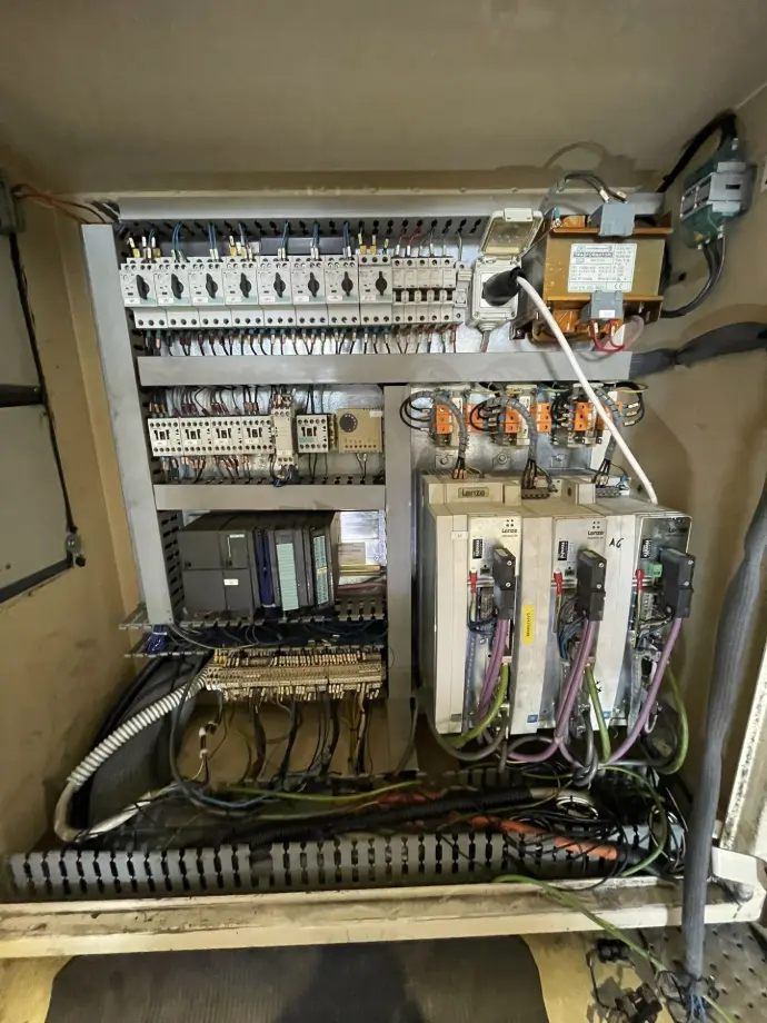
CONTROL CABINET
As part of the machine modernization, a new control cabinet was implemented with a focus on performance optimization and safety. All protective devices, control components, and power supplies were completely replaced. Lenze i750 frequency inverters were used, utilizing a bus-based power supply system Lenze i700 power supply. This concept allows multiple inverters (in this case three) to be connected to a single common i700 power supply module and protected by a single circuit breaker for the entire group. Such a solution provides significant space savings within the cabinet and reduces overall investment costs.
The control system was replaced with a new Lenze c520 PLC, which communicates with the frequency inverters via EtherCAT. The PLC was extended with digital input/output modules, analog current inputs a high-speed counter.
An industrial router was also integrated into the cabinet, enabling remote access to the system (service, diagnostics, updates) while also ensuring communication between the PLC and the HMI panel. On the operator panel, a Lenze v430 HMI display was installed, connected via Ethernet. The display is powered through PoE (Power over Ethernet), which allows the use of a single Ethernet cable for both data transfer and power supply. This simplifies cabling and increases overall system reliability.
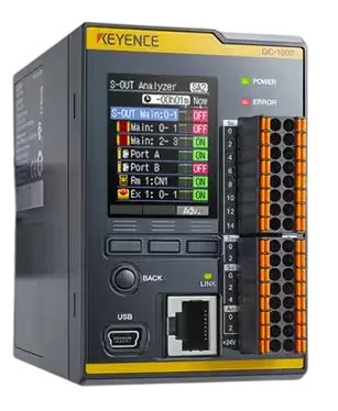
To enhance the machine’s functional safety, a Keyence GC-1000 safety relay was implemented. This device serves as the central unit for processing safety signals from sensors and safety devices. The relay is equipped with an integrated display that enables instant diagnostics of the safety circuit. This allows operators to quickly identify the type of fault, its location, and the current status of the safety devices. Furthermore, the relay provides real-time visualization of input and output states, which simplifies maintenance interventions and reduces machine downtime.
The use of this type of relay increases the reliability of the safety system and enables more efficient maintenance and faster troubleshooting.

PROGRAMMING AND VISUALIZATION
As part of the modernization, the machine’s control system was completely reprogrammed using standardized Lenze application blocks, ensuring higher modularity and reliability of control.
One of the main technical tasks was the synchronization of the machine with the preceding production line to prevent tubes from falling out during transfer. Synchronization was achieved based on a signal from the previous machine, routed to the PLC input module and processed by a high-speed counter.
A key element of the control system was also the coordination of two butterfly arms. These had to operate synchronously during the pickup and placement of tubes to avoid mutual mechanical collision. The motion timing had to be configured with high precision, since:
- the maximum available time for performing a single tube leak test is 2 seconds
- the production line speed reaches up to 160 tubes per minute.
The software solution also incorporated control and evaluation of the tube leak test process. The test is carried out by a pneumatic system that supplies compressed air into each tube and monitors pressure variations. The program provides automatic result classification:
- Defective tubes (with leakage) are identified and automatically ejected from the machine,
- Non-defective tubes are directed to further processing in the production line.
At the operator level, a Lenze v430 HMI interface was implemented, enabling:
- setting and adjusting machine operating parameters,
- monitoring the leak test status in real time,
- displaying diagnostic data, operating states, and fault messages.
The visualization was developed in VebVisu and provides the operator with a clear and intuitive interface for managing the entire technological process directly from the control panel.

